Electrical Systems & Specifications
Electrical Distribution Systems Under Division 26
Understand the path from incoming power to building loads, distinguish distribution equipment and check the connections, responsibilities and completion work in your estimate.
10 min read
Follow the power path from the incoming supply to the building's loads, and understand what each part contributes to a complete estimate.
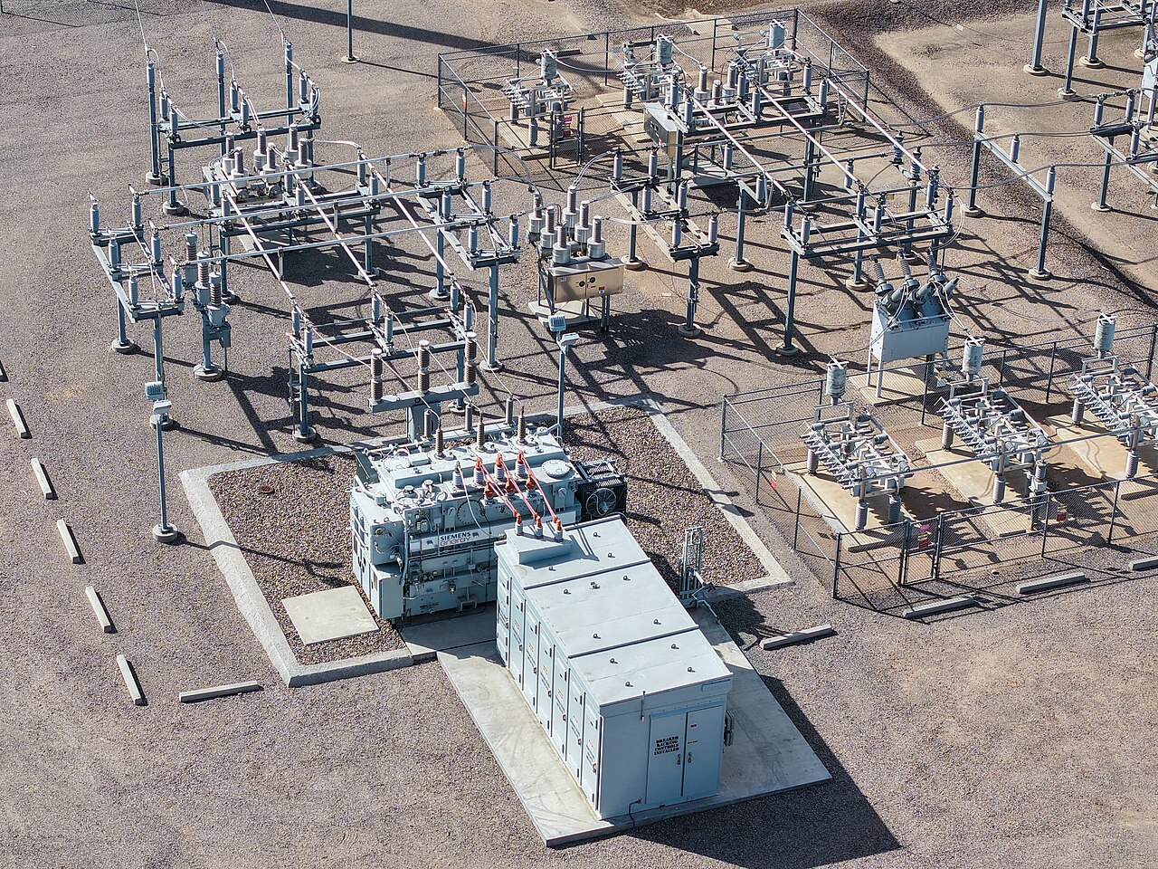
Distribution equipment at a substation. Photograph: Rsparks3, CC0. This is not the fictional building example or a Canadian design reference.
An electrical distribution system receives power and delivers it to equipment, lighting and other loads. The equipment names can look similar on a drawing, but a transformer, switchboard and panelboard do different jobs. Understanding those jobs helps an estimator read the design, compare quotations and identify missing work.
This article focuses on building distribution within Division 26. It explains the power path and the questions to resolve before pricing it. The project's drawings, specifications and utility requirements determine the actual arrangement.
1. Start at the incoming supply
First identify how the project receives electricity and where the contractor's work begins. A building may receive a low-voltage supply from a utility transformer, or have a primary-service arrangement with additional distribution equipment. Do not assume that every project starts with the same transformer or service equipment.
Two Canadian references show why the boundary matters:
- Hydro One's Conditions of Service, effective 1 May 2026, distinguishes ownership and operational demarcation points and describes different service arrangements. For general-service customers, it also calls for early consultation to confirm available voltages. [1]
- BC Hydro's switchgear guidance describes utility-owned primary distribution switchgear and the coordination needed with the customer's equipment. Utility equipment can be part of the connection arrangement without becoming a contractor-supplied item. [2]
These are examples from particular utilities, not national rules for every connection. Identify the serving utility and obtain the project-specific information.
Before carrying a service allowance, establish who provides the equipment, metering provisions, ducts, excavation, concrete, cables and terminations. Separate utility charges from contractor installation costs and identify who is responsible for each. The position of equipment on the site does not, by itself, establish ownership or pricing responsibility.
2. Recognise the main equipment
Read the equipment tag and the specification together. A tag such as “MDP” is a project identifier; it is not enough information to establish the equipment's construction or complete scope.
| Item | Its role in distribution | What to check in the estimate |
|---|---|---|
| Transformer | Changes the supply voltage to suit another part of the installation. Distribution transformers can serve downstream building loads at a different voltage. [3] | Primary and secondary voltages, phase, capacity, construction, enclosure, mounting, accessories and connections. |
| Switchgear | An assembly used for switching, protection and distribution. The term covers different equipment arrangements; utility primary switchgear is one example. [2, 4] | The specified equipment class, protective devices, controls, ratings, access requirements and installation arrangement. |
| Switchboard | Distributes power to downstream equipment or large loads, using the specified switching and protective devices. It can serve as service-entrance equipment where designed for that purpose. [4] | The complete lineup, main and outgoing devices, metering, cable-entry arrangements and the supplier's installation exclusions. |
| Panelboard | Divides an incoming supply into outgoing circuits through the specified protective devices. Panelboards can serve lighting, receptacles, equipment or downstream distribution. [5] | The schedule, incoming arrangement, bus rating, outgoing devices, spare provisions, enclosure and circuit identification. |
| Metering | Measures electrical quantities at the specified points. Utility revenue metering and owner monitoring can have different responsibilities. [1, 6] | Who supplies meters, instrument transformers, enclosures, wiring, communications and configuration where required. |
A switchboard is not simply another name for switchgear. Equally, a panelboard is not defined only by whether it serves lights. Eaton and ABB describe the equipment distinctions, but the project's specified assembly governs what is priced. [4, 5]
UBC's low-voltage transformer guidance provides a useful Canadian review example. It considers voltage and phase, loading, future capacity, environmental conditions, weight, ventilation, mounting and access. [3] These are useful prompts; UBC's specific equipment requirements are not automatically requirements for another owner's project.
3. Follow the connections between the equipment
Distribution equipment is only part of the installation. Every required power connection also needs to be identified.
On building drawings, a feeder commonly connects one distribution point to another, such as a main switchboard to a downstream panelboard. A branch circuit is the wiring between its final overcurrent protective device and the outlet or outlets it serves. [12] Use the project's schedules and circuit references to identify each connection; these descriptions are reading aids, not conductor-sizing instructions.
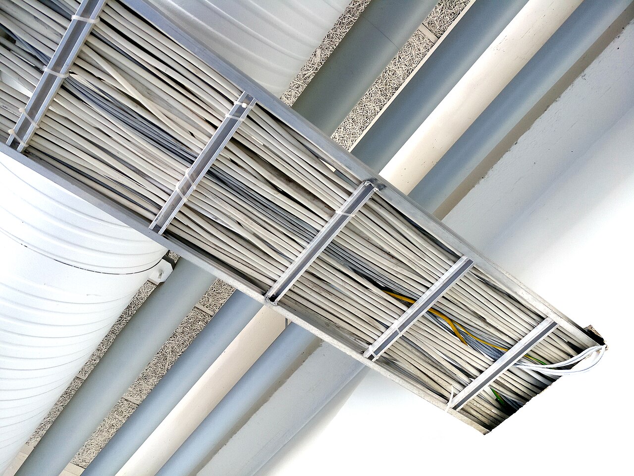
The specified route may use cables in conduit, cable tray or another wiring method, or a busway assembly. A busway distributes power through conductors enclosed in a manufactured assembly. It is not cable tray, which supports cables. [13]
For each connection, check:
- its source and destination;
- the specified conductors or busway, including quantity and arrangement;
- the route, rises, drops and entry positions;
- raceways, boxes, fittings and supports;
- terminations, bonding, identification and specified testing.
Count a feeder once, even when it appears on the single-line diagram and a floor plan. Use the single-line diagram to establish the connection and the layout drawings to measure its route. Resolve conflicting information through the tender clarification process.
4. Read the single-line diagram with the schedules
A single-line diagram summarises the electrical connections and distribution arrangement. It is not usually a scaled routing drawing. Read it alongside equipment schedules, panel schedules, layouts, details and the relevant specifications.
| Document | What to establish |
|---|---|
| Single-line diagram | Supply sources, connected equipment, protective devices and the path between them. |
| Equipment and panel schedules | Equipment characteristics, outgoing circuits, connected loads and required spare provisions. |
| Layouts and details | Locations, installation arrangements, routes, access and supporting work. |
| Specifications and addenda | Required construction, accessories, studies, testing, revisions and allocation of responsibilities. |
Keep ratings distinct. Voltage, current, transformer capacity and fault-duty requirements describe different characteristics. An equipment ampere rating alone does not establish its short-circuit suitability. Manufacturer documentation distinguishes equipment short-circuit ratings and protective-device interrupting ratings. [8]
For estimating, carry the specified requirements into the enquiry and compare the quotation against them. If a rating or protective-device requirement is missing or conflicts with another document, record the question. Do not silently select a different rating to complete the price.
5. Understand the distribution arrangement
The way equipment is connected affects the amount of equipment, cabling, control work and testing required.
A radial arrangement gives a load one supply path in the arrangement being considered. Other designs can use alternative sources, selectable supply paths or interconnected sections. Eaton's distribution guide describes several arrangements, including radial, loop-primary and selective systems. [7]
An alternative source does not automatically mean that every downstream load has uninterrupted power. Follow the actual connections, switching and operating sequence. Establish which loads are served from normal, standby or emergency sources as identified by the design.
Check whether a quotation includes the specified tie devices, transfer equipment, interlocks, controls and demonstrations. Do not substitute a simpler arrangement or assume two supplies operate in parallel. The engineer's design and the utility's requirements establish the intended operation.
6. Example: trace a transformer-fed panelboard
Assume a fictional commercial renovation receives a 600 V supply. Its drawings show main distribution equipment feeding a transformer with a 600 V primary and a 208Y/120 V secondary. The transformer then supplies a panelboard serving the indicated loads.
This is an illustrative arrangement, not a service recommendation or a sizing example. Such transformer voltage options are represented in Hammond Power Solutions' published material. [9]
Incoming supply → main distribution → transformer → panelboard → final circuits and loads
The real design also identifies the required protection, metering, grounding and bonding. Their positions and details are omitted from this simple reading aid.
| Part of the example | Pricing check |
|---|---|
| Main distribution equipment | Does the quotation include the required outgoing device for the transformer connection? |
| Transformer input | Have the feeder, route, supports and terminations been carried? |
| Transformer | Are the specified equipment, mounting, delivery and installation requirements covered? |
| Transformer output | Have the secondary connection and its required supporting work been identified? |
| Panelboard and final circuits | Does the price cover the scheduled panelboard and the outgoing circuits within the tender scope? |
| Completion | Who provides the specified testing, settings, identification, records and handover? |
The transformer quotation may cover only the transformer. A panelboard quotation may cover only the panelboard and listed devices. Neither quotation should be assumed to cover the cables between them.
If the supplier includes a connection accessory, record that inclusion before adding the same accessory to your own takeoff. If it excludes installation, identify where the corresponding labour is carried.
7. Include protection, bonding and completion work
Overcurrent protection and grounding and bonding are part of the distribution review, not optional extras to consider after the equipment total is assembled.
Technical Safety BC distinguishes grounding and bonding connections and explains a particular BC application. [10] The estimating lesson is to follow the specified connections through the complete installation. Do not treat a general “grounding included” note as proof that every required conductor, connection and accessory is covered.
Where the project requires a protection-coordination study, establish who performs it and who implements the resulting approved settings. Selective coordination concerns the operation of protective devices to limit the portion of the system disconnected by an abnormal condition. [11] This article does not prescribe where it is required or select protective devices.
Also check the specified testing, commissioning, identification, record drawings and operating information. Separate these activities where the documents treat them separately. Identify responsibilities for supplier attendance, shutdown coordination and utility connection work.
A distribution installation can be fully measured and still be incompletely priced if its studies, settings or completion activities have been omitted.
Before finalising the distribution price
Trace each required connection from its source to its destination. Reconcile equipment tags with schedules, reconcile supplier exclusions with your own takeoff, and check the work supporting each installation.
Resolve unclear responsibilities or obtain an authorised estimating decision consistent with the tender instructions before finalising the price. Keep the document reference and decision with the estimate so another reviewer can understand what has been included.
References
-
Hydro One: Conditions of Service, effective 1 May 2026, particularly sections 3.2.2–3.2.4. Utility-specific ownership, voltage and metering examples. The effective document is distinguished from the separately posted draft revisions.
-
BC Hydro: BC Hydro-owned switchgear. Primary distribution and utility coordination example; not a national allocation of scope.
-
UBC: Low-Voltage Transformers, November 2025, section 26 22 13. Owner-specific Canadian equipment review example.
-
Eaton Canada: Switchboard fundamentals. Switchboard roles and equipment distinctions.
-
ABB: What is a panelboard? Montréal, 25 June 2026. Canadian panelboard application explanation.
-
UBC: Secondary Power Distribution, November 2025, section 26 24 00. Owner-specific distribution requirements.
-
Eaton: Power Distribution Systems Design Guide overview. Arrangement and distribution-method overview, not Canadian code requirements.
-
Schneider Electric: What is the short circuit rating of my panelboard?. Manufacturer explanation of panelboard and protective-device ratings; no US code requirements adopted here.
-
Hammond Power Solutions: Typical transformer specification, SPS 10, section 2.2. Corroborates example voltage options only; its specialist product requirements are not adopted for the fictional example.
-
Technical Safety BC: Understanding Single Point Grounding, revision 2, 4 March 2025. BC terminology and application context; local requirements must be confirmed.
-
Schneider Electric: Selective Coordination. Functional explanation only; US regulatory requirements are not presented as Canadian requirements.
-
Technical Safety BC: Class A and B gas fitter—limited scope of electrical work, terminology. Used for the branch-circuit meaning only, not licensing advice.
-
Eaton: Fundamentals of low- and medium-voltage busway. Manufactured enclosed-busbar system explanation.
References checked 22 October 2026. This is educational estimating guidance, not an installation procedure or an electrical design. The example omits design details and does not establish equipment sizes, fault ratings, clearances or code compliance. Utility and owner documents apply within their own scopes; use the actual project requirements and applicable jurisdiction. MasterFormat is a registered trademark of CSI.
Photo credit
“Distribution substation switchgear” by Rsparks3, 14 March 2026, Wikimedia Commons. Released under CC0 1.0, used unchanged. The photograph shows substation equipment; it is not a photograph or design of the fictional building example and is not presented as a Canadian installation.
General estimating workflow guidance. Project requirements and contractual documents take precedence; this is not electrical design or code-compliance advice.