Electrical Systems & Specifications
Grounding and Bonding Under Division 26
Understand grounding and bonding under Division 26, including components, scope coordination, takeoff and testing considerations for electrical estimators.
7 min read
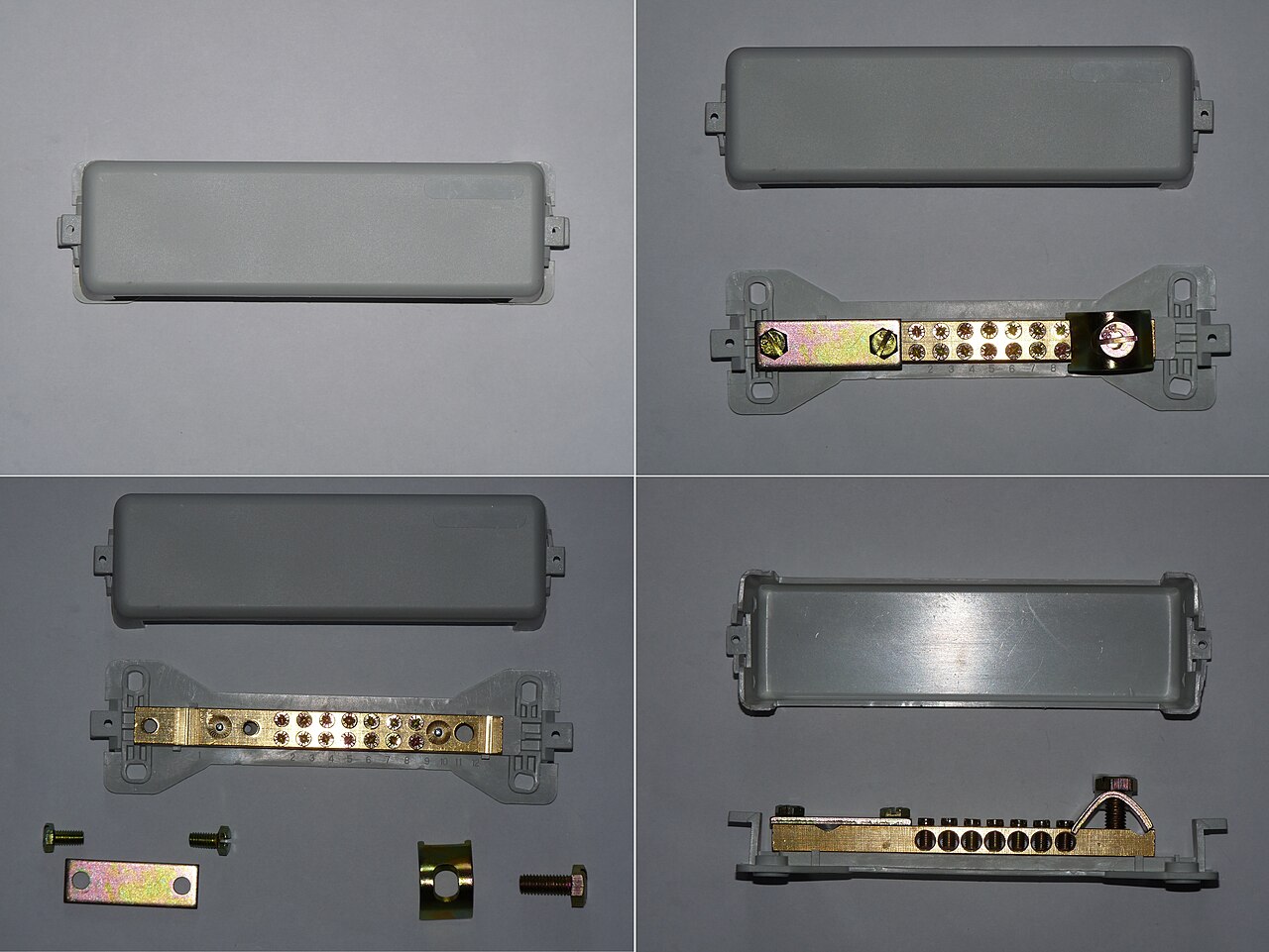
Illustrative component photograph; not a Canadian installation or compliance example. “Main earthing busbar” by Dmitry G, CC BY-SA 3.0. Wikimedia preview size.
Grounding and bonding often appear together in specifications, but they do different jobs. An estimate can include the visible grounding electrode and still miss bonding conductors, connections, busbars, testing or work assigned to another contractor.
This article explains permanent building systems at an introductory level. It is an estimating guide, not instructions for designing, sizing, installing or testing a system. Use the project documents and the electrical code adopted in the project’s province or territory, including local amendments and the authority having jurisdiction’s requirements.
1. Grounding and bonding have different purposes
Grounding connects a system or equipment to earth. It helps establish a reference to earth and limit voltage relative to earth. Bonding connects conductive parts together. In a typical solidly grounded building system, the equipment bonding arrangement provides a low-impedance path for fault current to return to its source. That path supports operation of the protective device. [1][2]
Fault current does not simply disappear into the soil. It returns to the source through available conductive paths. An electrode in the earth is not a substitute for the intended equipment bonding path. [1][2]
| Term | Plain-language meaning | Estimating question |
|---|---|---|
| Grounding electrode | A conductive component that makes the intended connection to earth | What electrode arrangement, excavation, connections and access are specified? |
| Grounding conductor | A conductor associated with the connection to the grounding electrode | Where does it run, and what protection and terminations are required? |
| Bonding conductor or jumper | A conductor that connects conductive parts as part of the bonding arrangement | Which equipment and connections require it, and is it separate from the cable or raceway assembly? |
| Grounding or bonding busbar | A common connection point for specified conductors | Who supplies it, mounts it, connects it and identifies it? |
These descriptions explain the functions. The applicable code and project specifications govern the exact terminology and arrangement.
2. Do not treat the neutral as another bonding conductor
A neutral conductor can carry current during normal operation. The protective bonding path is not intended to serve as the normal return path for load current.
The location of the connection between a grounded circuit conductor and the bonding arrangement matters. Additional connections in the wrong places can create parallel paths for neutral current through metalwork and bonding conductors. Technical Safety BC explains this issue in its single-point-grounding bulletin for solidly grounded AC systems supplied by a supply authority. [1]
That bulletin has a defined British Columbia scope. Do not turn it into a universal rule for every transformer, generator or other source arrangement. When drawings show multiple sources, ask the designer to confirm the intended grounding and bonding arrangement and include the specified work in the estimate.
3. Find the complete scope in Division 26
Start with the single-line diagram, grounding details, equipment schedules and specifications. Follow each shown connection to its destination. A note reading “ground equipment” is not enough information to determine every conductor route, connection method or trade responsibility.
Canadian specification systems do not always use the same section number for this work. UBC lists 26 05 26 — Grounding and Bonding. The National Research Council’s public National Master Specification descriptions include 26 05 27 — Grounding – Primary and 26 05 28 — Grounding – Secondary. Read the project’s actual section list rather than assuming one number contains the whole scope. [3][4]
Look for the specified electrode arrangement, conductors, busbars, equipment connections, cable-tray connections, bonding jumpers, connectors, identification and protection. Also check whether civil work, access boxes or connections to building components are shown. Include only what the documents and applicable requirements establish; raise questions where the arrangement is incomplete.
4. Coordinate connections with other systems
The electrical scope can meet the communications scope at a busbar, conductor or equipment connection. UBC’s technical guidelines list both Division 26 grounding and bonding and 27 05 26 — Bonding and Grounding for Communications Systems. That is a useful reminder to review both divisions. It does not establish the responsibility split for another project. [4]
For each shared connection, identify who supplies the component, installs it, connects each end and verifies the completed work. Apply the same review to security equipment, lightning protection and specialist equipment where the project documents show a connection.
For example, “provide a communications grounding busbar” leaves several questions unanswered: Does the electrical contractor supply the busbar? Who installs the conductor to it? Who bonds the racks? Who records the test results? Resolve those questions before pricing the work as complete.
5. Measure connections as well as conductor lengths
A useful takeoff separates the route from the work at each end. Ten metres of conductor with two straightforward terminations is a different task from ten metres with several equipment connections, difficult access and specialist connection methods.
| Scope item | What to confirm before pricing |
|---|---|
| Conductors | Specified size and material, route, length, installation method and physical protection |
| Connections | Quantity, compatible connector type, surface preparation and access |
| Busbars | Dimensions or specified product, mounting, connection capacity, labels and locations |
| Electrodes and buried work | Arrangement, installation conditions, excavation responsibility, reinstatement and inspection access |
| Equipment and raceway bonding | Required jumpers or other bonding provisions, connection points and packaged-equipment inclusions |
| Verification and records | Required tests, responsible party, witnessing, reports and handover documents |
Do not choose a smaller conductor or a different connection method to make the price fit. If information needed for pricing is missing, request clarification or record an authorised estimating decision consistent with the tender instructions.
6. Keep testing requirements separate
Checking continuity of a bonding connection and measuring resistance to earth address different parts of the installation. One result does not automatically prove the other part is satisfactory.
Confirm the specified test methods, acceptance criteria, timing, qualifications and reporting requirements. Include any required witnessing or coordination before equipment is energised. Do not insert a generic resistance target into the estimate because it appeared on another job.
A Canadian federal tender specification for an NRC laboratory fit-up provides a project example: its Grounding – Secondary section calls for continuity and resistance tests appropriate to the site, with the method subject to the engineer and local authority’s approval, before energising. Those are requirements of that project, not a national testing rule for every installation. [5]
7. Example: a communications-room fit-up
Consider a fictional fit-up that shows one communications-room busbar and two equipment racks. Division 26 shows the conductor to the busbar. Division 27 describes connections from the racks, but the tender documents do not clearly assign supply of the busbar or testing of the completed connections.
The estimator can measure the confirmed conductor route and the two documented rack connections. Record the unanswered scope questions separately: who supplies and mounts the busbar, and who performs and reports the required tests?
Assign each question to a person and record when the answer is needed. Before finalising the price, resolve the responsibility split or obtain an authorised estimating decision that follows the tender instructions. Avoid pricing the same connection twice or leaving it out because each contractor expected the other to include it.
8. What a complete estimate should explain
A reviewer should be able to follow the specified electrode arrangement, conductor routes, equipment connections and shared connections between contractors. They should also see what testing and records are included, which questions remain open and how those questions were addressed.
Grounding and bonding are easier to estimate when they are treated as a connected system. Count the components, trace the connections and confirm responsibility for the completed work.
References
[1] Technical Safety BC — Understanding Single Point Grounding, 4 March 2025, Revision 2. British Columbia guidance with a defined supply and system scope.
[2] BC Trades Modules — Construction Electrician, Level 1, G-3: Install Grounding and Bonding. Older training material, corrected January 2017, used for basic concepts only; its code references are not presented as current requirements.
[3] National Research Council Canada — NMS document descriptions. Public descriptions of primary and secondary grounding specification sections.
[4] University of British Columbia — Divisional Specifications. Public section index for electrical and communications grounding and bonding; UBC project requirements are not national requirements.
[5] CanadaBuys — NRC Advanced Manufacturing Program Lab Fit-Up tender package, Section 26 05 28, Grounding – Secondary, field quality control. A project-specific example.
Sources reviewed 28 October 2026. Confirm the code edition and requirements applicable to each project.
General estimating workflow guidance. Project requirements and contractual documents take precedence; this is not electrical design or code-compliance advice.