Electrical Systems & Specifications
Raceways, Conduits and Cable Trays Under Division 26
Understand electrical raceways, conduit and cable trays, with practical checks for routes, fittings, supports, penetrations and complete Division 26 estimates.
9 min read
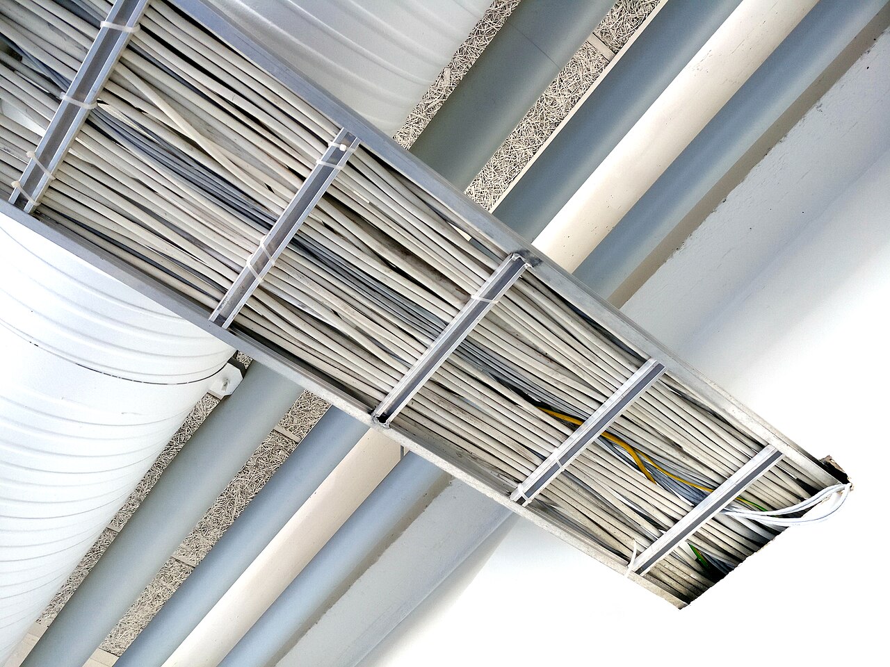
Illustrative photograph; not a Canadian installation or compliance example. “Cable tray with cables” by Santeri Viinamäki, CC BY-SA 4.0. Wikimedia preview size; no other changes.
A line on an electrical drawing can represent much more than a length of conduit or cable tray. The installed route may also need fittings, boxes, supports, bonding connections, sleeves, firestopping and work at each end.
The estimator’s job is to understand the specified wiring method and price the complete installation. Start with the drawings, specifications and schedules together. Use the electrical and building requirements adopted in the project’s province or territory, including local amendments and the authority having jurisdiction’s requirements. This overview explains scope and estimating considerations; it does not provide design or sizing instructions.
1. Understand what the pathway does
Raceway is a broad term for a channel intended to house electrical conductors or cables. Conduit, tubing, surface raceways and wireways have different constructions and requirements. EMT means electrical metallic tubing; although it is often called conduit on site, it is a distinct product type.
Cable tray supports cables along a route. Ladder, ventilated, solid-bottom and wire-mesh trays differ in construction. Treat tray as its own wiring-method review rather than assuming that the rules for enclosed conduit apply to it. Canadian training material and manufacturers’ technical guides distinguish these systems and their requirements. [1][2]
For estimating, separate the pathway from the wiring it carries. One tray can serve several cable runs. A conduit route can contain several conductors. Neither the tray length nor the conduit length automatically equals the total cable or conductor quantity.
2. Identify the specified system before measuring
Record the pathway type, size, material, finish and installation conditions. A takeoff item labelled only “conduit” leaves too much unanswered.
| System | What the estimator needs to identify |
|---|---|
| Electrical metallic tubing (EMT) | Trade size, specified tubing and fitting types, supports and conditions of use |
| Rigid metal conduit | Material, finish, connection method, fittings and any specified corrosion protection |
| Rigid PVC conduit | Product type, fittings, supports and provisions for temperature movement |
| Flexible or liquidtight conduit | Exact product type, connection length and compatible end fittings |
| Surface raceway or wireway | Profile, covers, bends, device fittings, boxes and any specified compartments |
| Cable tray | Tray construction, width, depth, material, load rating, fittings, supports and accessories |
These are items to confirm, not a list of interchangeable options. Canadian manufacturer catalogues identify separate fitting families for rigid conduit, EMT, flexible conduit and liquidtight systems. IPEX’s rigid PVC literature also identifies expansion fittings and the need to accommodate temperature movement. Price the system specified for the location rather than substituting another type because it has a lower material price. [3][4]
3. Read the project’s section list
The National Research Council’s April 2026 National Master Specification table of contents lists 26 05 34 — Conduits, Conduit Fastenings and Conduit Fittings and 26 05 36 — Cable Trays for Electrical Systems. It also lists related sections for supports, boxes, raceways and wireways. [5]
A project can organise this work differently. For example, Metrolinx’s September 2025 Section 26 05 34, Raceway for Electrical Systems, includes cable-tray requirements. Read the actual project section, its related sections and the division of work; do not rely on a familiar section number alone. [6]
Also check Division 27 when a pathway serves communications cabling. A tray’s location on an electrical drawing does not, by itself, establish who supplies it, installs it or pulls the cables.
4. Measure the installed route and its changes
Trace the route from its starting point to its destination. Check plan views against sections, equipment elevations and ceiling information. Record vertical rises, drops and offsets as well as the horizontal distance.
For example, a fictional route includes an 18 m corridor run, 6 m into a room and a 3 m rise. Those stated segments total 27 m. If the design calls for two separate conduits following that route, they represent 54 m of conduit, before any further adjustment needed for the final route and fitting geometry. They do not represent 54 m of every conductor.
Count changes in direction, branches, reductions, entries and terminations separately, or show clearly that their material and labour are already included in an assembly rate. Avoid both omissions and duplicate pricing.
Review the proposed pulling arrangement as well. Conductor fill, bends between pulling points, box dimensions and cable bending requirements need a compliant design. If the information needed for pricing is missing or the route appears impractical, request clarification rather than selecting a convenient box or conduit size yourself.
5. Treat cable tray as a complete support system
A tray takeoff needs more than the straight sections. ABB’s technical guide describes different tray constructions, materials, supports, fittings, expansion joints, dividers and covers. The specified arrangement determines which components belong in the estimate. [2]
Separate straight tray from elbows, tees, reducers, risers, dropouts and other accessories. Identify covers where specified, including covers for fittings. Check the support arrangement, structural attachment, required restraint and access for installing and maintaining the cables.
The cable installation needs its own review. Confirm that the specified cable type, loading, spacing and securing arrangement suit the tray and its location. Spare space shown on a drawing is not permission to add any cable or exceed the system’s loading limits. Do not apply one fill percentage or support spacing to every tray system.
At a transition from tray to conduit or equipment, identify the specified support, cable protection and bonding provisions. A complete price must reach the equipment connection, not stop where the main tray ends.
6. Check the building conditions and trade responsibilities
The same measured length can require very different labour in an accessible plant room, above an occupied ceiling or in a congested service corridor. Check working height, access equipment, shutdowns, sequencing and protection of existing finishes when they apply.
Roof areas deserve particular attention. Technical Safety BC’s bulletin on raceways and cables below roof systems warns that roof installation or repair can damage wiring located near the roof deck. Confirm the project’s routing and protection requirements; the bulletin is British Columbia guidance, not a clearance rule for every Canadian project. [7]
Penetrations also need a defined scope. NRC project firestopping specifications describe systems for openings containing cables, trays and conduits, with components tied to a listed system design. Establish the required assembly, opening and penetrating services before pricing a generic amount of sealant. Ordinary sealing and firestopping are different scope items. [8]
| Connection or responsibility | Question to resolve |
|---|---|
| Structural supports | Who designs, supplies and installs supports, anchors and any required seismic restraint? |
| Openings and sleeves | Who forms or drills openings, supplies sleeves and reinstates finishes? |
| Rated penetrations | Who selects the applicable firestop system, installs it, inspects it and provides records? |
| Communications pathways | Who provides tray, conduit, pull boxes, bonding and transitions to racks or outlets? |
| Cable installation | Is pulling or laying cable included with the pathway work, or priced separately? |
| Completion | Who provides identification, specified checks, cleaning, as-built information and handover records? |
Owner requirements can change the answer. UBC Vancouver’s communications-pathway specification, for example, restricts sharing supports with line-voltage wiring and sets access and coordination requirements for communications trays. Those are UBC requirements to review on applicable projects, not a responsibility split to assume elsewhere. [9]
7. Example of a scope gap at the end of a tray
Consider a fictional fit-out with 30 m of cable tray in a corridor and four conduit drops into equipment rooms. Each drop is shown as 4 m long, giving 16 m of conduit, measured separately from the 30 m of tray.
An estimate containing only those two lengths is still incomplete. It needs the specified tray and conduit fittings, supports, entries and connections. The estimator also needs to establish who provides sleeves and firestopping where the route crosses rated construction, and whether cable installation is included in the same package.
Measure the confirmed work and record each unanswered question, its owner and the date an answer is needed. Before finalising the price, resolve the scope or obtain an authorised estimating decision that follows the tender instructions. Do not assume that another trade has included a connection simply because its equipment is at the other end.
8. Review the complete installation
A reviewer should be able to trace each route, identify its specified system and understand the quantities and labour included. Check that fittings, supports, boxes, transitions, bonding, penetrations and completion work are either priced explicitly or included in clearly described assemblies.
Keep measured installed quantities separate from purchasing allowances and standard-length ordering. Record what remains uncertain and how it was addressed. A complete pathway estimate explains how the wiring gets from one point to the next, including the work needed along the way.
References
[1] BC Trades Modules — Construction Electrician, Level 3, G-1, raceway and wiring-method overview. Older training material used for introductory terminology only; its code tables and rule references are not presented as current requirements.
[2] ABB — Cable Tray Technical Guide, tray types, materials and installation components. The guide includes both Canadian and US material; this article uses its product and component descriptions, not its NEC provisions or numerical installation limits.
[3] ABB Electrification Canada — Industrial Fittings, product-family catalogue.
[4] IPEX — Scepter Rigid PVC Conduit and Fittings, fittings and thermal movement. Manufacturer guidance for the specified product must be checked for each application.
[5] National Research Council Canada — NMS table of contents, April 2026, Division 26 section titles.
[6] Metrolinx — Raceway for Electrical Systems, Section 26 05 34, September 2025. An owner specification, not a national installation standard.
[7] Technical Safety BC — Protection of electrical raceways and cables under roof systems and decks, 5 October 2022, Revision 2.
[8] CanadaBuys — NRC tender package, Fire Stopping, Section 07 84 00, March 2023, definitions and listed systems. A project-specific example.
[9] UBC Vancouver — Communications Pathways, Section 27 05 28, November 2025 revision, cable trays and coordination.
Sources reviewed 30 October 2026. Confirm the applicable code edition, project requirements and current manufacturer instructions before pricing the work.
General estimating workflow guidance. Project requirements and contractual documents take precedence; this is not electrical design or code-compliance advice.